
At the heart of nearly every process plant lies a component whose performance quietly dictates the efficiency and profitability of the entire operation: the heat exchanger. A successful design is invisible, operating flawlessly for years. A poor design, however, becomes a chronic source of problems—escalating energy costs, production bottlenecks, and plant shutdowns that should never have happened. The difference between these two scenarios isn’t luck; it’s the precision and rigor applied at the most critical stage: thermal design.
Understanding the fundamentals of shell and tube heat exchanger thermal design is not just an exercise for engineers; it is a strategic necessity for any manager looking to optimize costs and mitigate risks. In this guide, we will break down the process, the hidden dangers, and how modern engineering is replacing assumptions with certainty through an optimized heat exchanger thermal design.
How technical decisions impact the bottom line
Every decision in thermal design has a direct financial consequence. These are not abstract concepts but factors that directly impact capital investment (CAPEX), operating costs (OPEX), and the overall risk of the project.
The area dilemma (A): An insufficient transfer area will fail to meet the thermal duty (Q), creating a permanent bottleneck in your process. An excessive area, often the result of conservative “safety margins,” means inflated CAPEX in expensive materials and a larger installation footprint.
The tyranny of pressure drop (ΔP): A high pressure drop, often resulting from poor baffle design or high velocities, translates directly into higher energy consumption by pumps throughout the equipment’s entire service life. It’s an operational tax you pay 24/7.
The silent enemy (fouling): A design that fails to properly account for the nature of the fluid and its velocities can accelerate the accumulation of deposits (fouling). This not only degrades performance but also imposes a cycle of cleaning shutdowns, impacting productivity and increasing maintenance costs.
The fundamentals: The governing equation Q = U⋅A⋅ΔTlm
The entire discipline comes down to solving this fundamental equation. While Q (the heat to be transferred) and ΔTlm (the driving force) are defined by the process, the true art of engineering lies in the U⋅A term. The engineer must not only provide sufficient area (A) but must also configure a geometry (tube diameter, spacing, baffle type) that yields the highest possible overall heat transfer coefficient (U), without violating the critical constraint of the allowable pressure drop.
The thermal design process: A step-by-step approach
Step 1: Define process requirements
It all starts with the problem to be solved. We need to know: the fluids involved (hot and cold), mass flow rates, desired inlet and outlet temperatures, and the maximum operating pressure and allowable pressure drop (ΔP).
Step 2: Obtain physical properties
The properties of the fluids (density, viscosity, specific heat, thermal conductivity) change with temperature. It is crucial to obtain accurate data at operating conditions for the calculations to be valid.
Step 3: Calculate thermal duty (Q) and ΔTlm
With the data from Step 1, the total heat to be transferred (Q) and the log mean temperature difference (ΔTlm) are calculated. The latter will depend on whether the flow is co-current or counter-current.
Step 4: Estimate the overall coefficient (U)
This is where experience comes in. An initial value for U is assumed based on the type of fluids and prior experience. This value will be verified later.
Step 5: Calculate the required area (A)
With Q, U, and ΔTlm, a preliminary heat transfer area is calculated.
Step 6: Define geometry and verify
This is the most complex phase and where TEMA (Tubular Exchanger Manufacturers Association) standards are applied. The following must be selected:
Diameter, length, and number of tubes
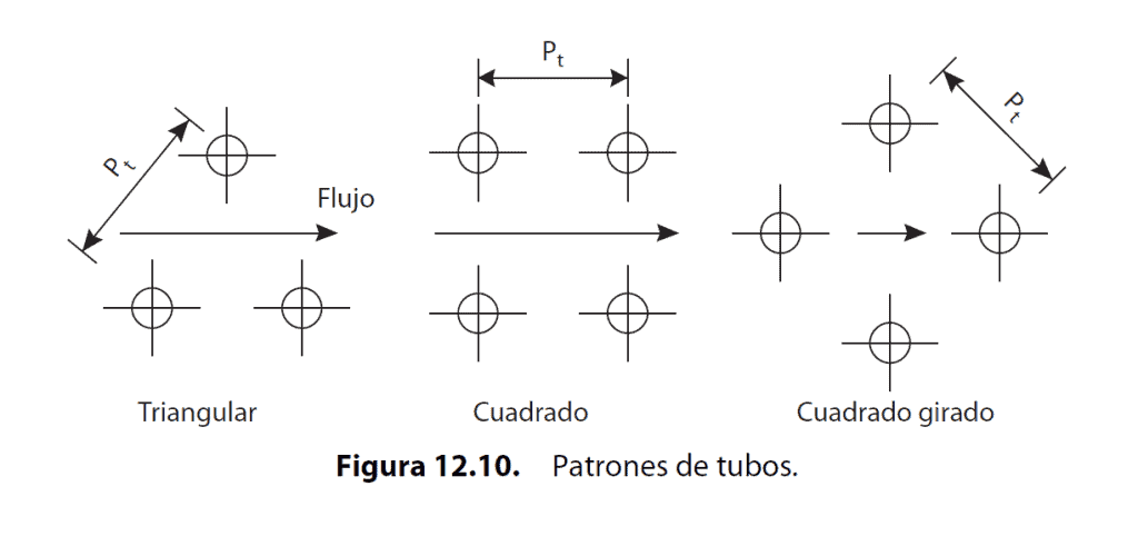
Tube layout (pitch)
Shell diameter
Type and spacing of baffles
With a defined geometry, the individual heat transfer coefficients are calculated to obtain a calculated value of U. If this value is close to the assumed value, the design is viable. If not, one must go back and adjust the geometry. This iterative process is where experience makes all the difference. To ensure optimal convergence and a design that balances performance and cost, consult our specialized engineering services.
Finally, it is verified that the pressure drop (ΔP) on both the shell and tube sides is within the allowable limits.
Hidden dangers: Design flaws that lead to failure
Beyond simply failing to meet the thermal duty, more catastrophic failures exist:
Flow-induced vibration (FIV): Excessive fluid velocities on the shell side can cause tubes to vibrate, leading to fatigue failure or tubes being cut by collision with the baffles.
Poor flow distribution: A poor design of the inlet nozzles or baffle spacing can create dead zones or channeling, where a large portion of the transfer area becomes ineffective.
Material incompatibility: The incorrect selection of materials for the operating conditions (temperature, pressure, fluid corrosivity) is a primary cause of premature failure.
Conclusion
The thermal design of a heat exchanger is one of the most critical engineering levers for controlling the efficiency and reliability of an industrial process. A superficial approach leads to hidden costs and operational risks, while a rigorous, methodical design that balances all the described variables is the only way to secure a high-performance asset with a low total cost of ownership.