At the heart of every distillation column in the chemical, petrochemical, or refining industry lies a critical piece of equipment: the reboiler. Its function is simple in theory—to generate the vapor that drives the separation—but the reality of its design and operation is profoundly complex. An incorrect design decision at this stage can create a domino effect of financial and operational consequences that affect the profitability of the entire plant.
The central problem is not whether the reboiler will work, but how efficiently it will do so throughout its service life. A suboptimal design, often based on empirical methods or rules of thumb, introduces risks and inefficiencies that directly impact the bottom line. At JAZAM, we understand that a correct specification and an expert-led Kettle reboiler design is the cornerstone of an efficient and profitable process.
Below, we break down the essential principles, classification, and design considerations that every engineering and plant management professional should know about Kettle reboiler design.
The hidden cost of a suboptimal reboiler design
We understand that plant management and administration professionals focus on tangible results. A suboptimal reboiler design, while seeming like a technical detail, has direct and significant consequences on your business indicators:
Impact on capital expenditure (CAPEX): A conservative and imprecise approach leads to oversizing. Consider a scenario: a traditional design with a 30% safety margin in the transfer area results in a Kettle reboiler design costing 500,000 USD. An optimized design using advanced simulation might have shown that only a 10% margin was needed, reducing the equipment’s size and cost by 15-20%—a saving of 75,000 to 100,000 USD in CAPEX on a single unit.
Impact on operating costs (OPEX): A design that does not adequately consider fouling or internal hydraulics will require more energy to meet its thermal duty. A 10% increase in medium-pressure steam consumption to compensate for efficiency loss due to fouling can translate into tens of thousands of dollars in additional energy costs per year. Furthermore, more frequent cleaning cycles increase maintenance costs and chemical consumption.
Risk of downtime: This is the most costly threat. An unplanned failure of the reboiler, whether due to unforeseen vibrations, severe fouling, or control problems, can shut down an entire production unit. In the petrochemical industry, the cost of downtime can exceed 260,000 USD per hour. A single day of lost production can cost more than 6 million dollars, completely overshadowing any initial savings in the Kettle reboiler design.
Definition and primary function
The Kettle-type reboiler, also known as a submerged-bundle reboiler, is a specialized class of shell-and-tube heat exchanger. Its design is optimized for a primary and critical function in countless industrial processes: supplying the latent heat of vaporization needed at the base of distillation or fractionation columns, or in any process requiring the controlled generation of vapor from a liquid stream. Its main objective is to generate the vapor flow that rises through the column, providing the driving force for the separation of a mixture’s components based on their relative volatilities.
A fundamental characteristic that distinguishes the Kettle-type reboiler from other configurations, such as thermosyphons, is its ability to return high-purity vapor, virtually free of entrained liquid, to the column. This is because the separation of the vapor and liquid phases occurs within the oversized shell of the unit itself, a deliberate design feature that makes it more than just a simple heat exchanger.
This intrinsic phase separation design positions the Kettle reboiler not only as a heat transfer device but as an autonomous process unit that functions, in essence, as an equilibrium stage or an ideal theoretical plate. The vapor returning to the tower and the liquid exiting as the bottoms product are in thermodynamic equilibrium. This particularity has profound implications for the overall system design. Unlike thermosyphon reboilers, which return a two-phase mixture and require separation to occur at the bottom of the column, the Kettle significantly simplifies the design of the tower base, eliminating the need for complex internal separation baffles. However, this simplicity in the column is transferred to the reboiler itself, which is consequently larger, heavier, and more expensive than its thermosyphon counterparts. The choice of a Kettle, therefore, represents a fundamental engineering decision about where to locate the complexity and cost of the system: in the column or in the reboiling equipment.
Industrial context and role as critical equipment
The manufacturing and design of shell-and-tube heat exchangers are rigorously governed by international standards to ensure safety, reliability, and interchangeability.
TEMA standards (Tubular Exchanger Manufacturers Association): TEMA provides the guidelines for mechanical design, manufacturing, and tolerances. Its three-letter nomenclature is the universal language for describing an exchanger’s configuration. In this nomenclature, the central letter defines the shell type. The “K” shell type specifically refers to the Kettle configuration. This designation implies a horizontal shell with an internal tube bundle and an expanded vapor dome for phase separation, with its application being almost exclusive to reboilers. TEMA also establishes classes (R, C, B) that define the level of robustness and manufacturing requirements according to the severity of the service (petroleum, chemical, general).
ASME code (American Society of Mechanical Engineers): While TEMA focuses on configuration and best practices, the ASME code (specifically Section VIII, Division 1) governs the design of pressure vessels. This includes calculating the thickness of the shell, heads, tubesheets, and nozzles to safely contain the design pressure. The ASME UHX section contains specific rules for the design of heat exchangers, complementing TEMA’s guidelines to ensure the structural integrity of pressure-bearing components. An exchanger with an ASME stamp guarantees that it has been designed, manufactured, and inspected in accordance with these rigorous safety requirements.
Mechanical configuration and operating principles
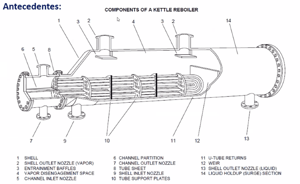
To fully understand the operation of a Kettle reboiler, it is essential to analyze its anatomy. Although it shares elements with conventional shell-and-tube exchangers, its components are adapted to fulfill its dual function of heat transfer and phase separation. A typical schematic diagram, based on TEMA descriptions and technical literature, reveals a unique configuration.
The oversized shell (TEMA K-Shell): The most distinctive component is the horizontal shell, whose diameter is considerably larger than that of the tube bundle. This geometry creates two well-defined functional zones:
Boiling zone: The lower section of the shell, which houses the tube bundle, forms a “kettle” or “pot” that contains a pool of boiling liquid. The tube bundle typically occupies between 40% and 60% of the shell’s internal diameter.
Vapor dome: The large free space at the top, above the liquid level, acts as a separation dome. This volume allows the velocity of the rising vapor to decrease, facilitating the gravitational dropout of entrained liquid droplets before the vapor exits through the top nozzle.
This deliberate shell design represents a paradigm shift compared to conventional heat exchangers. In a standard exchanger, the shell design and baffle arrangement seek to optimize flow velocity and pattern to maximize forced convection heat transfer. In a Kettle, the objective is the opposite: the shell-side fluid is practically static, and baffles are not used to direct the flow; their function, if they exist, is merely for structural support of the tubes. Therefore, Kettle reboiler design is not an optimization of flow hydraulics but a management of volumes and interfacial surfaces to ensure stable boiling and efficient phase separation.
The tube bundle: The tube bundle is the heart of the heat transfer. The two most common configurations are:
U-tube bundle (TEMA U-tube): This is a very popular option, especially when the heating fluid is clean, like steam. Its main advantage is that, since the tubes are fixed to a single tubesheet, the bundle can expand and contract freely with temperature changes, eliminating the need for expansion joints or complex floating heads. This makes it more economical. Its main disadvantage is the difficulty of performing mechanical cleaning inside the U-bends.
Straight tube bundle with floating head (TEMA S, T, etc.): This configuration uses straight tubes that pass through two tubesheets, one fixed and one “floating” inside the shell. It allows for differential thermal expansion and, crucially, the complete removal of the tube bundle for both internal and external inspection and mechanical cleaning. It is the preferred option for services where fouling is anticipated in either fluid, although it is a more complex and costly construction.
The overflow weir: This is a simple but vitally important internal component. It is a vertical plate or dam installed near the end of the shell, on the side of the bottoms product outlet. Its function is to maintain a constant, predetermined liquid level within the shell, ensuring that the tube bundle remains fully submerged at all times, even during operational fluctuations. The liquid arriving from the column fills the kettle until the level exceeds the weir’s height; the excess spills over it and is removed as the bottoms product. The design and calculation of the weir height are key steps in sizing the reboiler.
Nozzles and demisters: The arrangement of nozzles is critical for proper operation. Typically, there is an inlet nozzle for the process liquid from the column, a large-diameter outlet nozzle at the top of the dome for the vapor return, and an outlet nozzle for the liquid bottoms after the overflow weir. For services requiring extremely high vapor purity, a demister pad, which is a mesh pad of metal or other material, can be installed in the vapor outlet nozzle. This device intercepts and coalesces any liquid micro-droplets that may be entrained by the vapor, ensuring a virtually dry vapor return to the column.
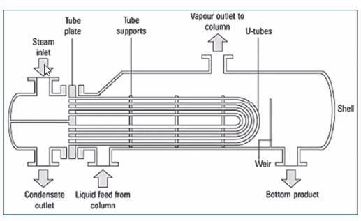
Flow diagram
The flow pattern in a Kettle reboiler is consistent and defines its operation.
Tubeside (hot fluid): The heating medium, which is usually pressurized steam (condensing) or a thermal fluid like hot oil (sensible cooling), circulates inside the tube bundle. It enters through the head, travels the length of the tubes (in one or more passes), and exits through the same or another head.
Shellside (process fluid): The liquid to be vaporized, coming from the bottom of the distillation column, enters the shell and floods the tube bundle, forming a pool of liquid. Heat is transferred through the tube walls to this liquid, causing it to boil on the outer surface of the tubes.
Phase equilibrium and the theoretical stage
The magic of the Kettle reboiler lies in its ability to act as a thermodynamic equilibrium stage. As the process liquid boils on the surface of the tubes, a vapor stream is generated. Due to the large area of the liquid-vapor interface and the generous volume of the dome, the vapor separates efficiently from the liquid by gravity.
The vapor, which becomes enriched in the more volatile components, accumulates in the dome and exits through the top nozzle to return to the distillation column. Simultaneously, the remaining liquid, which has become depleted of the more volatile components, flows over the overflow weir and is removed as the bottoms product. Due to this intimate contact and subsequent separation, the exiting vapor and the liquid overflowing the weir are considered to be in phase equilibrium. This feature is an immense operational and design advantage, as the Kettle reboiler behaves like a perfect theoretical plate, simplifying the simulation calculations for the distillation column and contributing predictably and stably to the separation process.
Common design errors and their business consequences (summary)
A poor design can lead to chronic operational problems that erode profitability. Identifying these common errors is the first step to avoiding them.
Ignoring fouling potential:
The error: Selecting a triangular tube pitch for a service with a fluid that has a tendency to foul, even if moderate. The decision is based on a lower initial CAPEX due to the more compact equipment size.
Business consequence: To compensate, operators must increase the heating steam temperature, increasing energy OPEX. Eventually, the equipment must be taken out of service for costly and intensive chemical cleaning. This translates to unplanned plant shutdowns, lost production, and a much shorter and more expensive asset lifecycle.
Incorrect sizing of the vapor dome:
The error: Underestimating the volume required for phase separation, resulting in a vapor dome that is too small for the generated vapor load.
Business consequence: The column cannot achieve the specified product purity, leading to off-spec products that must be reprocessed (increasing OPEX) or sold at a lower price. In the worst-case scenario, the instability caused by flooding can force a unit shutdown, with massive losses from downtime.
Poor or poorly calibrated level control:
The error: Relying on a single, poorly maintained, or poorly calibrated level instrument.
Business consequence: Both scenarios lead to costly, unplanned plant shutdowns. Flooding requires time to stabilize the system, while a damaged tube bundle means a complete replacement, a significant CAPEX expense, and prolonged downtime.
Avoid costly errors in Kettle reboiler design. Request a consultation with our specialists to ensure the reliability of your investment.
The JAZAM advantage: mitigating risks with advanced simulation
Traditional design methods, based on empirical correlations and large safety margins, are no longer sufficient in a competitive environment. These approaches often lead to the aforementioned errors, resulting in oversized, inefficient, and failure-prone equipment.
At JAZAM, we have adopted a philosophy of “design based on predictive certainty.” Instead of relying on assumptions, we use state-of-the-art process simulation tools, such as ASPEN EDR (Exchanger Design and Rating), to rigorously model every aspect of the reboiler’s performance before a single piece of metal is fabricated.
What is predictive certainty?
Predictive certainty is the ability to anticipate with high accuracy how a piece of equipment will behave under real and variable operating conditions. ASPEN EDR allows us to achieve this by:
Integrating rigorous thermodynamics: Accessing the world’s largest physical property database, ensuring that phase equilibrium and fluid property calculations are accurate for any process mixture.
Modeling complex thermo-hydraulics: Going beyond simplified correlations. ASPEN EDR’s models, backed by research from HTFS (Heat Transfer and Fluid Flow Service), simulate internal circulation, convective and nucleate boiling, and two-phase flow profiles, providing a complete picture of what is happening inside the equipment.
Analyzing multiple scenarios: Allowing for the simulation of performance under different operating conditions (turndown, changes in feed composition, etc.), identifying potential bottlenecks and operational problems before they occur in the plant.
This simulation capability dramatically reduces project risk, ensuring that the final design is not only safe but also optimized for efficiency and reliability, thereby protecting our clients’ investment.
High-level conclusions and recommendations
The Kettle reboiler design is a robust and fundamental piece of engineering in the process industry. Its detailed analysis reveals an inherent duality: its design, which prioritizes stability and reliability, is also the source of its main operational challenges.
Synthesis of fundamental principles
The Kettle reboiler design focuses on volume management and phase separation rather than on optimizing fluid velocity. The oversized shell, vapor dome, and overflow weir work together to function as an ideal equilibrium stage, a feature that gives it exceptional operational reliability and flexibility (turndown), unsurpassed by other types of reboilers.
However, this strength comes at a cost. The large volume of liquid with low circulation velocities creates an environment conducive to fouling, which is its main weakness. Furthermore, its large size and weight translate into a high capital cost.
Therefore, the selection of a Kettle-type reboiler is a strategic decision that must weigh these factors. A Kettle is chosen not because it is the cheapest or most thermally efficient option in the abstract, but because process stability, long-term reliability, and operational flexibility are prioritized over initial CAPEX or maintenance frequency.
Key recommendations for design and operation
Based on the exhaustive analysis, the following key recommendations are proposed for the design, operation, and optimization of Kettle reboilers:
Use appropriate design models: Avoid using simplistic stagnant pool boiling correlations. Employ more rigorous models like the Palen & Small model or, ideally, HTRI’s circulation models, which recognize the convective nature of the process within the bundle.
Rigorously size the vapor dome: Pay special attention to the calculation of the shell diameter and dome height. Use criteria such as the Souders-Brown equation for the maximum vapor velocity and ensure adequate freeboard to prevent liquid entrainment, which degrades column efficiency.
Select the tube pitch strategically: The choice between triangular and square pitch should be based on a life-cycle cost analysis. For clean fluids, triangular pitch is more economical. For fluids with even the slightest fouling tendency, the investment in a square pitch is justified by the drastic reduction in maintenance costs and downtime.
Analyze vibrations (FIV): For large or high-duty units, perform a flow-induced vibration analysis, especially for U-tube bundles, to ensure sufficient supports are included and to prevent fatigue failures.
Critical level control: The liquid level control in the reboiler is the most critical variable for safe operation. Ensuring the reliability of the instrumentation (transmitters, calibration) is paramount to protect both the integrity of the tube bundle (avoiding exposure) and the operation of the column (avoiding flooding).
Proactive fouling monitoring: Implement a system to monitor the heat transfer coefficient (U) over time. A decrease in U is a direct indicator of fouling. Use this information to plan cleaning shutdowns proactively, not reactively.
Venting of non-condensables: Ensure that the heating steam system has an effective and operational venting system to continuously purge non-condensable gases, whose accumulation can collapse the reboiler’s performance.
Evaluate enhanced surfaces: In applications where maximizing efficiency is sought or where the ΔT is limited, consider using enhanced surface tubes (e.g., High-Flux). Perform a complete cost-benefit analysis, as their cost is higher and they can be more sensitive to certain types of fouling.
Consider advanced geometries: For services with severe fouling, explore technologies like Twisted Tubes®, which have been shown to improve circulation and reduce fouling rates, extending operating cycles.
Implement advanced process control (APC): In complex systems, the implementation of APC can unlock significant optimization potential, allowing for more profitable and efficient operation that cannot be achieved with basic control loops.