At the heart of every industrial process operates a silent and costly enemy: fouling in heat exchangers. This phenomenon, the progressive accumulation of unwanted deposits on heat transfer surfaces, is the root cause of countless operational overruns and unscheduled plant shutdowns. It is a critical artery that slowly clogs, choking the performance, efficiency, and profitability of your operation.
For a manager, fouling translates directly into higher energy bills, unforeseen maintenance cycles, and reduced production capacity, hitting the OPEX hard. For an engineer, it means a constant battle against increasing pressure drop and poor thermal performance. At JAZAM, we understand that the most cost-effective solution is not a late reaction with expensive cleanings, but strategic anticipation. The key lies in an expert design that anticipates the problem from the outset. This definitive guide will provide you with the tools to diagnose, combat, and, most importantly, design fouling-resistant systems.
Diagnosing the problem: 4 key indicators that fouling is at play
Detecting fouling early is essential to controlling its costs. To quantify its impact, you must monitor these four key indicators in your equipment:
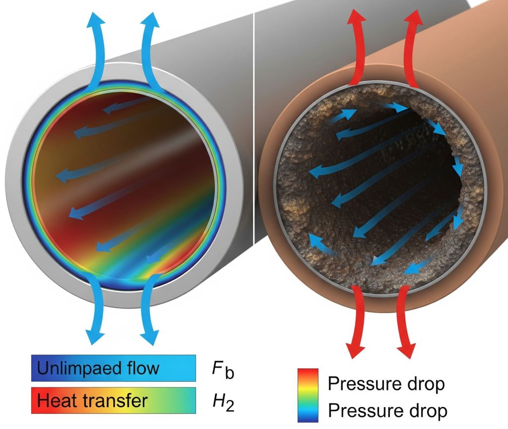
1. Increased pressure drop (ΔP)
This is the first and most obvious symptom. If the pressure drop in your equipment increases above design values without a change in flow rate, it is irrefutable proof of a physical obstruction. Particles or deposits reduce the flow area, forcing pumps to work harder to maintain the process. This is not just a technical indicator; it is a direct, measurable expense on your electricity bill and a risk to the integrity of your pumping system.
2. Reduction in the overall heat transfer coefficient (Uo)
This is the definitive sign of a loss in thermal performance. Typical fouling factors (Rf) may seem small, on the order of 10⁻⁴ m²·°C/W, but their effect is devastating: they are equivalent to adding a 0.2 mm thick layer of limestone, a very effective insulator. A decrease in the Uo value indicates that one of these layers is impeding heat flow.
The correct procedure to verify this is done using specialized simulation software like Aspen EDR. By entering the current operating parameters (flow rates, temperatures) and the exact geometry of the equipment into a rating module, the software calculates the actual degree of fouling. This analysis precisely reveals how much the Uo coefficient has decreased compared to its clean design state. Understanding how to apply the complete guide to heat exchanger fouling: diagnosis, prevention, and robust design is crucial for the equipment’s longevity. If you suspect a loss of performance but lack the tools to quantify it, request an evaluation of your equipment with our specialists.
3. Variation in process outlet temperatures
This is a direct symptom that the exchanger no longer meets its thermal duty (Q). The fouling layer acts as an insulator, preventing the equipment from doing the job it was designed for. This manifests in two ways: the hot fluid fails to cool to its design temperature (it exits hotter than expected), or vice versa, the cold fluid does not reach its target temperature (it exits colder than it should). Either of these scenarios can cause quality problems, poor performance in later process stages, and a general waste of energy.
4. Accelerated cleaning and maintenance cycles
From a business perspective, this is one of the most painful indicators. Tabulated fouling factors, like those from Kern, aim to ensure an operating period of 1 to 1.5 years between cleanings. However, this time is a reference and can vary drastically depending on the severity of the fluids in question. If your equipment requires maintenance shutdowns much more frequently than planned for its specific service, it is an unmistakable sign that the fouling is more severe than estimated in the design, directly affecting profitability.
Anatomy of the enemy: the mechanisms of fouling
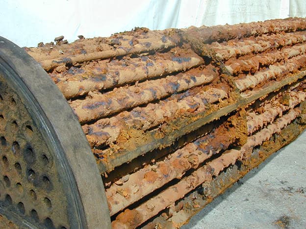
To combat fouling, you must first understand its nature. It manifests through six main mechanisms that often act in concert:
Crystallization: Formation of solid deposits like calcium carbonate, especially when the solubility of salts decreases with increasing temperature.
Particulate fouling (sedimentation): Accumulation of suspended particles such as sludge, rust, or sand on the surface.
Chemical reaction: Products of reactions on the surface, such as the thermal degradation of crude oils at high wall temperatures.
Corrosion: Formation of oxides or by-products of the metal’s own corrosion that adhere to the surface.
Biological: Growth of microorganisms like algae and fungi, common in systems with cooling water.
Freezing/solidification: Solidification of a fluid component on a cold surface.
The battle plan: a robust design as the first line of defense
The fight against fouling is won at the design table. A robust engineering approach can dramatically minimize the rate of fouling. A proper understanding of this complete guide to heat exchanger fouling: diagnosis, prevention, and robust design is the first step.
1. Strategic fluid allocation
Dirty fluid on the tubeside: Whenever possible, the fluid with the highest fouling potential should circulate inside the tubes to facilitate mechanical cleaning.
Viscous fluid on the shellside: To minimize pressure drop, highly viscous fluids benefit from the larger cross-flow area offered by the shell side.
High-pressure fluid on the tubeside: For safety and cost, it is preferable to contain high pressures within the tubes.
2. Rigorous velocity control
Velocity is critical. It must be high enough to “sweep away” deposits but without causing damage.
Reference ranges: For liquids, between 0.7 and 7 m/s; for gases, from 3 to 30 m/s. For cooling water, 2 m/s in tubes is recommended to mitigate fouling.
Limits and responsibility: TEMA does not limit erosional velocities, but as engineers, it is our duty to avoid them to prevent vibrations and wear. A good practice is to limit the pressure drop in nozzles to no more than 5% of the total ΔP for liquids and 12% for vapor.
3. Smart selection of materials and geometry
Materials: The correct choice of metallurgy is fundamental. Carbon steels like SA 516 are used for high stress, but for corrosive services, alloyed or stainless steels must be used, meeting strict standards like ISO 15156 or NACE-MR0103.
Geometry: For very dirty fluids, 1-inch diameter tubes are recommended. Baffle cuts are typically 20-40%. Impingement plates at the nozzles are essential and required by TEMA to protect the tubes from erosion.
4. Efficient operation and maintenance practices
Pre-treatment: Installing filters or separators before the exchanger is an investment that protects the entire system.
Scheduled cleaning: Use methods appropriate for the type of fouling, like chemical or mechanical cleaning.
Critical safety precaution: Never clean individual tubes with steam. The differential thermal expansion can generate enormous stresses and permanently damage the equipment.
The JAZAM advantage: from simulation to predictive certainty
Tools like Aspen EDR are powerful, but their value depends on the engineer’s expertise. The use modes are explained below to understand their power.
The power of simulation: rating, design and simulation
Rating: This mode is used to verify the performance of an existing heat exchanger. The exact dimensions and current operating conditions are entered to calculate actual performance and quantify the effect of fouling. It is ideal for diagnosing problems.
Design: This is used to create a new heat exchanger from scratch. Process parameters are entered, and the software proposes the optimal geometry to meet the requirements efficiently.
Simulation: This is used to predict how an existing design will behave under different conditions by performing “what-if…” studies, which is invaluable for optimizing operations.
At JAZAM, we don’t just use these tools; we integrate them into a rigorous process. We validate the results with plant data and, if necessary, with a second simulator. We don’t deliver a calculation, but predictive certainty, mitigating your investment risk (CAPEX) and operational risk (OPEX). Discover how our simulation-validated design approach can bring certainty to your project.
Conclusion: Your first line of defense is design
Fouling is not an unavoidable fate; it is an engineering challenge that can be controlled and mitigated. While operational practices are important, the most impactful and cost-effective battle is won before the first plate is welded. A proactive, intelligent, and simulation-validated design is the single most important factor in guaranteeing a long, efficient, and profitable life for your heat exchanger. Applying the principles from the complete guide to heat exchanger fouling: diagnosis, prevention, and robust design is the first step towards operational excellence.